- 您现在的位置:买卖IC网 > Sheet目录1994 > DS1672S-3/T&R (Maxim Integrated Products)IC TIMEKEEPER 3V 32-BIT 8-SOIC
DS1672
11 of 15
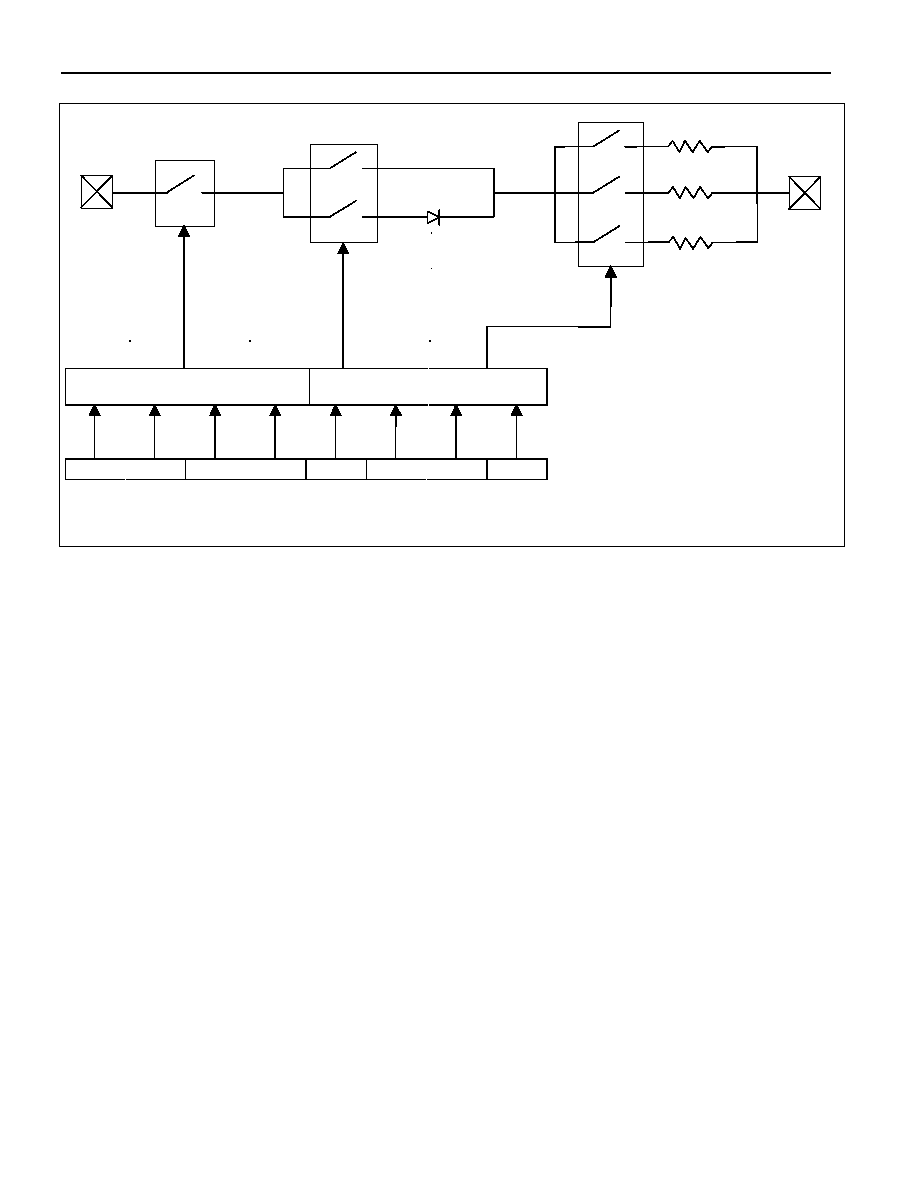
Figure 5. Programmable Trickle Charger
I
2C Serial Data Bus
The DS1672 supports a bidirectional I
2C bus and data transmission protocol. A device that sends data
onto the bus is defined as a transmitter and a device receiving data as a receiver. The device that controls
the message is called a master. The devices that are controlled by the master are slaves. The bus must be
controlled by a master device that generates the serial clock (SCL), controls the bus access, and generates
the START and STOP conditions. The DS1672 operates as a slave on the I
2C bus. Connections to the bus
are made via the open-drain I/O lines SDA and SCL. Within the bus specifications, a standard mode
(100kHz maximum clock rate) and a fast mode (400kHz maximum clock rate) are defined. The DS1672
operates in both modes.
The following bus protocol has been defined (Figure 6):
Data transfer may be initiated only when the bus is not busy.
During data transfer, the data line must remain stable whenever the clock line is HIGH. Changes in
the data line while the clock line is high will be interpreted as control signals.
Accordingly, the following bus conditions have been defined:
Bus not busy: Both data and clock lines remain HIGH.
Start data transfer: A change in the state of the data line from high to low, while the clock line is
high, defines a START condition.
Stop data transfer: A change in the state of the data line from low to high, while the clock line is
high, defines a STOP condition.
1 OF 16 SELECT
NOTE: ONLY 1010 ENABLES
1 OF 2
SELECT
1 OF 3
SELECT
TCS
DS
RS
BIT 7
BIT 6
BIT 5
BIT 4
BIT 3
BIT 2
BIT 1
BIT 0
250
R1
R2
TRICKLE CHARGE REGISTER
TCS = TRICKLE CHARGER SELECT
DS = DIODE SELECT
RS = RESISTOR SELECT
VCC
VBACKUP
2k
R3
4k
发布紧急采购,3分钟左右您将得到回复。
相关PDF资料
DS1673S-3
IC CTRLR SYSTEM PORT 3V 20-SOIC
DS1677E
IC CTRLR SYSTEM PORT 20-TSSOP
DS1678S/T&R
IC RECORDER REALTIME EVENT 8SOIC
DS1682S
IC TIMEKEEPER ALARM ELAPSE 8SOIC
DS1683S+T&R
IC REAL TIME EVENT REC 8SOIC
DS1685EN-5/T&R
IC RTC 5V 64BIT Y2K IND 24TSSOP
DS1688S+
IC RTC W/NV RAM CTRL 28-SOIC
DS1689SN+T&R
IC RTC SER NV RAM CTRL IN 28SOIC
相关代理商/技术参数
DS1672S-3/TR
制造商:MAXIM 制造商全称:Maxim Integrated Products 功能描述:I2C 32-Bit Binary Counter RTC
DS1672S-3+
功能描述:实时时钟 I2C 32-Bit Binary Counter RTC RoHS:否 制造商:Microchip Technology 功能:Clock, Calendar. Alarm RTC 总线接口:I2C 日期格式:DW:DM:M:Y 时间格式:HH:MM:SS RTC 存储容量:64 B 电源电压-最大:5.5 V 电源电压-最小:1.8 V 最大工作温度:+ 85 C 最小工作温度: 安装风格:Through Hole 封装 / 箱体:PDIP-8 封装:Tube
DS1672S-3+T&R
制造商:Maxim Integrated Products 功能描述:REAL TIME CLOCK SERL 8SOIC - Tape and Reel 制造商:Maxim Integrated Products 功能描述:IC TIMEKEEPER 3V 32-BIT 8-SOIC 制造商:Maxim Integrated Products 功能描述:Real Time Clock I2C 32-Bit Binary Counter RTC
DS1672S-3+T&R
功能描述:实时时钟 I2C 32-Bit Binary Counter RTC RoHS:否 制造商:Microchip Technology 功能:Clock, Calendar. Alarm RTC 总线接口:I2C 日期格式:DW:DM:M:Y 时间格式:HH:MM:SS RTC 存储容量:64 B 电源电压-最大:5.5 V 电源电压-最小:1.8 V 最大工作温度:+ 85 C 最小工作温度: 安装风格:Through Hole 封装 / 箱体:PDIP-8 封装:Tube
DS1672S-3+TR
制造商:MAXIM 制造商全称:Maxim Integrated Products 功能描述:I2C 32-Bit Binary Counter RTC
DS1672S-33
功能描述:实时时钟 I2C 32-Bit Binary Counter RTC RoHS:否 制造商:Microchip Technology 功能:Clock, Calendar. Alarm RTC 总线接口:I2C 日期格式:DW:DM:M:Y 时间格式:HH:MM:SS RTC 存储容量:64 B 电源电压-最大:5.5 V 电源电压-最小:1.8 V 最大工作温度:+ 85 C 最小工作温度: 安装风格:Through Hole 封装 / 箱体:PDIP-8 封装:Tube
DS1672S-33/T&R
制造商:Maxim Integrated Products 功能描述:REAL TIME CLOCK SERL 8SOIC - Tape and Reel 制造商:Maxim Integrated Products 功能描述:IC TIMEKEEPER 3.3V 32-BIT 8-SOIC 制造商:Maxim Integrated Products 功能描述:Real Time Clock I2C 32-Bit Binary Counter RTC
DS1672S-33/T&R
功能描述:实时时钟 I2C 32-Bit Binary Counter RTC RoHS:否 制造商:Microchip Technology 功能:Clock, Calendar. Alarm RTC 总线接口:I2C 日期格式:DW:DM:M:Y 时间格式:HH:MM:SS RTC 存储容量:64 B 电源电压-最大:5.5 V 电源电压-最小:1.8 V 最大工作温度:+ 85 C 最小工作温度: 安装风格:Through Hole 封装 / 箱体:PDIP-8 封装:Tube